To operate a vehicle on propane autogas as either a dedicated fuel or dual-fuel vehicle (i.e., switching between gasoline and propane), only a few modifications to the vehicle must be made. Until recently, propane autogas powered vehicles have commonly used a vapor pressure system that was somewhat similar to an old carburetor system, wherein the propane would be vaporized and mixed with combustion air in the intake plenum of the engine. This leads to lower engine output, as the vaporized propane displaces air, which would normally be consumed by the engine.A more recent approach is in the form of multi-port liquid injection that is capable of delivering liquid propane autogas directly into each cylinder’s intake port. Such a system will improve breathing efficiency and thereby lead to overall improved engine performance. When injected in this way, the fuel displaces significantly less air in the engine, and lowers the temperature of the air charge, which increases its density. Because propane autogas does not occupy a significant amount of volume within the intake, the performance of the engine will not be reduced. Furthermore, the fuel will vaporize as it mixes with the air, absorbing energy from the air, lowering the air’s temperature and ultimately increasing its density, again increasing performance. This advantage over a gaseous system eliminates the need for forced induction in order to maintain performance.
The single greatest drawback of a liquid injection system is problems associated with maintaining the propane autogas in a liquid state up to the injectors, given the operational temperature of the engine. This issue is addressed within the ROUSH CleanTech liquid propane autogas fuel system.
Fill Line Components
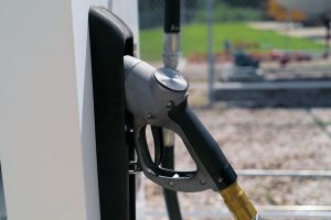
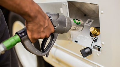
External Fill Valve

The fill valve is an industry-standard valve used to fill the vehicle with propane. It is design to be a safe passage for liquid propane to enter the vehicle, while including a check valve that prevents the fuel from escaping into the atmosphere.
Fill Filter

The fill filter is located between the fill valve and the fuel tank. It contains a five micron filter element that removes particles and contaminates from the fuel before entering the tank, preserving the life of components inside the tank.
Fuel Line Assembly
The ROUSH CleanTech liquid propane autogas fuel system features a return fuel system. The return line contains a flow control solenoid, either as a single component (as shown in Figure 1), or incorporated in a multi-function Fuel Rail Pressure Control Module, as shown in Figure 3 (FRPCM). The flow control solenoid is used by the Powertrain Control Module (PCM) to control fuel pressure in the fuel rail in order to ensure there is liquid propane in the fuel rail. The solenoid is a normally closed solenoid with an orifice drilled between the inlet and outlet ports of the solenoid body to permit some flow back to the tank when the solenoid is closed. When the solenoid is energized, the orifice is bypassed and return fuel flow to the tank is increased. The flow control solenoid can be seen in the upper left corner of Figure 1.

Figure 1: Fuel Rail Assembly and Flow Control Solenoid
Fuel Lines

The fuel lines in ROUSH CleanTech vehicles are made of high-durability stainless steel to handle the varying temperatures and pressures of liquid propane. They are designed to route through the vehicle in the factory fuel line locations.
Fuel Rail Assembly
The ROUSH CleanTech liquid propane autogas fuel system uses two symmetrical billet aluminum rail halves. Each rail half is fitted with four propane autogas specific fuel injectors. One rail half is fitted with an injection pressure and temperature sensor (IPTS). This sensor contains an OEM spec thermistor and a 0-500 psi pressure transducer.
Fuel Rails

ROUSH CleanTech’s signature blue anodized aluminum fuel rails are designed to operate under the varying temperatures and pressures of liquid propane. Fuel is regulated from the tank by the FRPCM (Fuel Rail Pressure Control Module) then sent through the rails. Fuel is then injected into the engine by each of the ten fuel injectors (6.8L V-10 pictured.) Un-used fuel returns through the FRPCM and flows back into the fuel tank.
Fuel Rail Pressure Control Module

The FRPCM controls the flow of liquid propane to and from the fuel rails by opening and closing a group of solenoids depending on engine demand and conditions. It plays a large role in making ROUSH CleanTech vehicles perform and feel exactly like their gasoline equivalents.
Fuel Tank Assembly
The ROUSH CleanTech liquid propane autogas fuel system, as designed for the 2009 and newer Ford E-450 cutaway, will utilize a dual manifold tank and occupies the same vehicle package envelop as the OEM gasoline tank that it replaces. The tanks are manufactured from ductile steel and certified to ASME standards. Refer to Figures 2 & 3.

Figure 2: Ford E-series Fuel Tank Assembly

Figure 3: Ford E-450 Fuel Tank Assembly as installed in vehicle frame
In order to transfer the liquid propane autogas fuel from the tank to the engine, the fuel tank assembly contains a fuel pump assembly powered by the Powertrain Control Module (PCM) as it would in the OEM gasoline vehicle application.
A total of three fuel filters are used with the fuel tank assembly. One filter is located external to the tank and is contained within the fuel fill line between the tank and fill valve. Two additional filters are located inside of the tank, one at the fuel pump inlet and the other at the fuel pump outlet.
The tank contains a fuel level sender resistor card and a unique fuel level sender float arm designed to match the output profile of the OEM fuel level sender. Internal tank baffles and a jet pump are used to maximize fuel pickup and delivery during low fuel conditions and extreme vehicle dynamic maneuvers.
Fuel Pump Assembly

The fuel pump assembly contains two fuel pumps (in the white center housing) and two fuel filters (in silver). Fuel passes through a filter sock in the bottom of the tank before entering the pumps. After passing through the silver filters, fuel is sent to the supply valve, where it will leave the tank and be pumped to the engine.
Supply Valve

The supply valve allows the flow of liquid propane to pass from the inside of the tank to the outside, sending it through the fuel supply line, which connects in place of the yellow plug. Flow is turned on and off by the supply solenoid (in black and silver). There is also a manual shutoff thumbscrew for use when servicing the fuel system.
Return Valve

Not all of the fuel sent to the engine is used. The remainder is sent through the fuel return line and into the tank, through the return valve. The return line connects in place of the gray cap.
Bleeder Valve

The bleeder valve provides a safe method to empty the tank for service. It is connected to an internal tube running to the 80% fuel level of the tank, ensuring that only vapor emits from the valve. It can also be used as a backup method to verify that the tank is not filled beyond the regulated 80% level.
Mechanical Fill Valve

When filling the vehicle, new fuel first passes through an external filter (not pictured) and then into the tank through the fill valve. The valve contains a float inside the tank that will close the valve and stop the flow of fuel when it reaches the regulated 80% level.
Fuel Pump Wire Harness Pass-Through

12v power and ground enter the tank through this sealed pass-through, allowing a safe power connection to the internal fuel pump.
Fuel Level Sender

The fuel level sender contains a float to measure the fuel level inside the tank. That information is sent to the vehicle’s instrument cluster and displayed on the factory fuel gauge. The fuel level sender also has a mechanical gauge on the outside of the tank to display the fuel level visually.
Powertrain Control Module
Control System Strategy
The ROUSH CleanTech liquid propane autogas strategy is built off of the OEM strategy with the addition of new logic to drive and monitor the flow control solenoid. Because the strategy is based off of the OEM strategy, the OEM PCM retains all fuel control and diagnostic functions. No modifications are made to the scan tool interface features of the logic except to add the propane autogas specific DTC’s. The propane autogas DTC’s are stored in the PCM memory and are cleared via the OEM strategy’s fault state controller.
Calibration
Changes to the OEM calibration are made in the following areas:
Engine:
- Modified I/O scaling as required
- Modified spark and fueling functions as required by physical properties of propane
Transmission:
- No changes required
Diagnostics:
- Disable (Ford F-150, Ford F-250 / Ford 350) or modify purge monitor and related component monitors